
Wet Exhaust System Design - Developing Basic Design Rules.
- Oct 31, 2022
- 4 min read
Updated: May 8, 2023
Our Owners Rep, Akan Dumrul, is a valuable asset, a Mechanical Engineer with an academic penchant. Come the time to critique the wet exhaust system design, and he rightly asked for my opinion. Hmm, I did not have one![*]. Akan was less than appreciative of my clueless stance, so it was time to hit the web and get an "edumication," as they say in the Southern USA. I turned to a few sources.
Boat wet exhaust system resources:
Trawler Forum is an excellent resource of old salts. They actively assist the hapless or witless until we learn to walk.
SetSail.com. Steve and Linda Dashew's experience designing and testing 17 variations of FPB.
Steve D'Antonio, you have to admit he's very experienced and willing to share.
The last one is Tony Athens of Seaboard Marine. His writing is directly to the point, experienced, and "don't waste my time." Probably my favorite "go-to" for marine fuel and exhaust knowledge.


To some extent, what we have to play with will dictate the final wet exhaust system. We wanted a quiet yacht so sound reduction was important. No longer does my youth beg for the roar of an engine exhaust. A quick search revealed typical sound suppression figures from 40% for single chamber lift systems through 80% for a dual chamber system. The latter are often fitted to gensets to stop the constant "woosh woosh" noise of water discharge. Our engine suits one within the sizes offered. Any noise above about 75dB is going to be annoying. Sea water is injected in to the exhaust at some point downstream of the turbocharger and dry side of the exhaust system. We then developed a set of overarching rules for the yard to work within. They are not immutable, but there should be a good reason to change: convenience is not a good reason.
Water Exhaust System Design - Basic Rules
Here are the rules we have distilled from the combined knowledge of the great and good referenced above.
Water should NEVER be allowed to enter the engine or turbocharger, EVER.
Water injection AFTER the downturn in the exhaust, angled down from the horizontal and NOT near the apex or before.
If anything might crack, assume it will. Mounts will fail if subject to bending moments, valves will similarly always fail at some point. A water-cooled header will crack at some point in time. Avoid using an anti-siphon valve as these need maintenance.
Avoid a "lift" type system requiring exhaust pressure to push cooling water up and out of the yacht. These add back pressure and penalise engine efficiency, we have the install advantage of engine room height and gravity is our protector from a flooded engine.
The exhaust system downstream of the water injector can NEVER run hot. Fit an over-temperature alarm..
Anything discharging above the waterline does not need a valve (especially as the exhaust riser is high). Anything discharging below the waterline needs a good quality ship-side valve (I like the glass reinforced composite ones for an aluminum hull).
316L Steel or Marine Type approved high temperature silicone exhaust hose are suitable for wet exhaust pipe.
The turbocharger and hot exhaust need an effective and liquid proof exhaust blanket or wrap.
Look at Yacht Resources
We selected a large, dual chamber combined water separator and muffler from Halyard. It sits on the wet side of the exhaust system. I believe hull No 1 also used the same or similar. Halyard supplied ancillary components such as the water injection head, expansion joints, dry riser and temperature sensor. We will experience a space penalty but also claimed <80% sound suppression with a lightly rated engine. The challenge now is to find somewhere for them in an already crowded engine room. We do not need to keep on the engine C/L as we won't heel like a yacht. Equipment can sit in front of the mufflers to save space as they are low-maintenance items.
Look at Building Vanguard Yacht
Wet Exhaust System Diagram
Look at Yacht Equipment


Water Exhaust Drawing shows a Dual separator and muffler omitting the additional water drain from the first chamber.

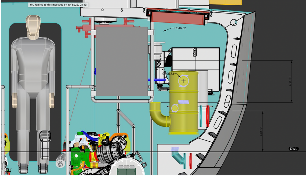
Water Exhaust Diagram Drawing shows development checking the fall from water injector and lift height above the waterline.
How does a marine wet exhaust system work?
These units separate water & exhaust in the first chamber. Water is discharged below the waterline and exhaust passes an additional resonating chamber before discharge overboard. It sits above the waterline and does not lift the fluids causing resultant back pressure penalty. The drawing also shows that there is further scope to move the unit outboard by about 300mm removing the redundant exhaust outlet valve creating more useable space in the engine room.
Wet exhaust system injection point


Similarly, as the injection point is significantly above the waterline, it does not require an anti siphon valve and attendant maintenance. Keep it simple and stupid.
So there we have it. A quiet, simple wet exhaust system, that meets our criteria and tucks neatly out of the way. It is essentially maintenance free and doubly protects the engine from sea water back flow from any source.
For such an ostensibly simple system, it's surprising how much thinking was used in the consideration of this install. Our Blog has been through about 6 reviews, I now want it gone so have posted twice weekly. I hope it helps our readers at some point in their own boat building journey. Time for some alcohol!
Akan Dumrul
Chris Leigh-Jones
For anyone interested in more general guidelines around marine exhaust systems, please find Halyard Installation Instructions in the file below.
(*)
Water exhaust systems
I've only ever messed with three marine exhaust systems. The first was one. 30,000 tonne geared bulk carrier landed me near blind in a hospital in Lake Charles, Louisiana, with acid burns to my eyes (real fun). The second was an experimental seawater scrubber we fitted to P&O Ferries vessel Pride of Kent, overseen by UK MCA. And the third, a much larger 4MW scrubber on Holland America's Zaandam (long story).
Look at Our Journey