
Weekly Update - Victron Nail It With An Integrated 220VAC Power System.
- Nov 10, 2023
- 5 min read
It's been a while since our 220 VAC this system had much attention but now is time to review and test the major components. There is nothing particularly novel in the design excluding a three phase integration.
Be warned, it is a mind game; you may get a headache reading it.
Power Input and Conversion
Solar: Four Victron Solar Smart MPPT controllers each take power from one of four large solar array (total 6kW Pmax) .

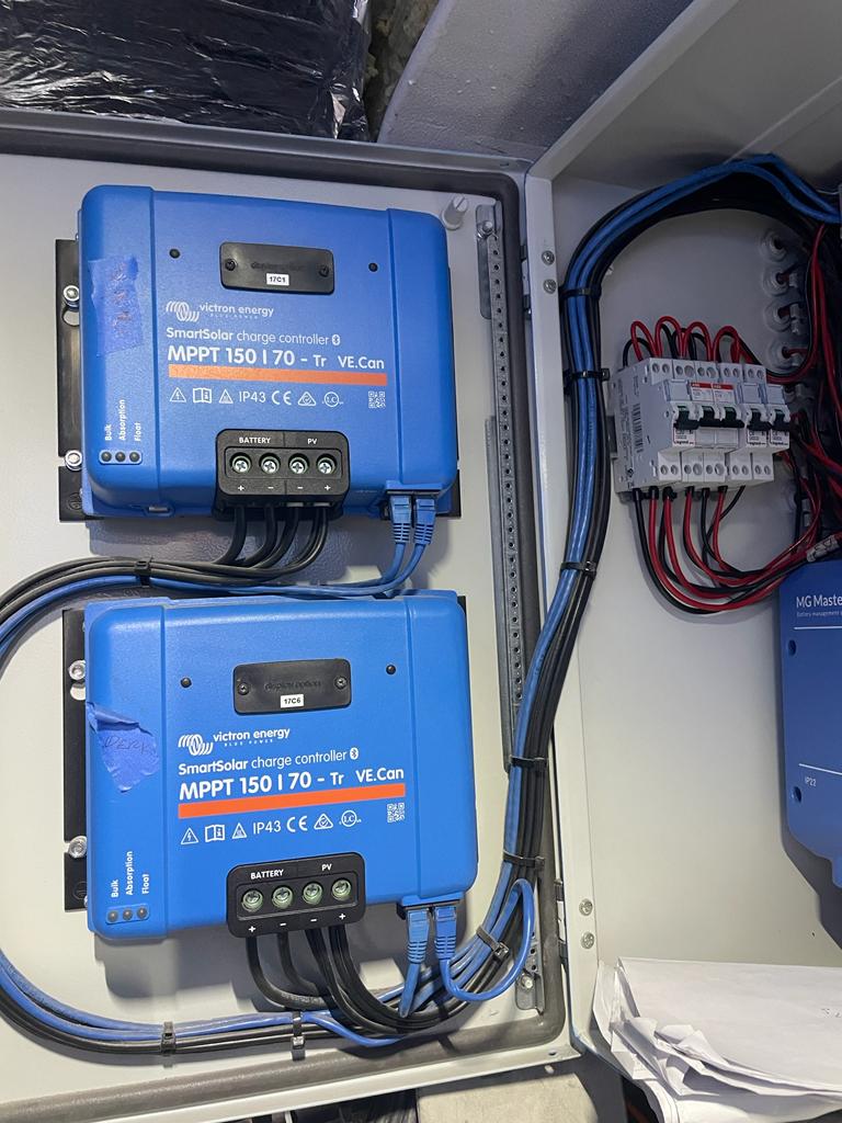
Solar panels are arranged into four groups in series/parallel to create 96VDC maximum voltage such that shading effects are limited and we remain within voltage safety limits. Solar output is converted to 24VDC.
All electrical connections are on the underside of each panel and away from potential trips or other electrical hazards. They connect to the system via an MG Systems battery management system that houses the main DC Bus Bars.
As Solar panels are always "live", each is fed through a dedicated breaker for future maintenance.
Shore Power - Victron Skylla-i - these are two single-phase unidirectional isolation
transformers in parallel, controlled from a single Skylla-i Control unit.
They accept 120VAC 60Hz to 220VAC 50Hz shore power and convert it to 100 Amp (max) 24VDC output. Conversion wastes some energy but makes us independent of single-phase shore power frequency (50/60 Hz). Skylla also provides galvanic isolation for the hull from any stray electrical currents in the dock. Input current can be limited to save continually tripping shoreside breakers.


(We can charge from 3-phase shore power 50 or 60Hz, though that is outside the scope of this Blog.)
Three-phase from Propulsion Batteries - MultiPlus inverter charger - these inverters are bi-directional. In other words, energy can flow both ways. They take power from 415VAC bus bars for 220VAC and 24VDC distribution. One Victron Multiplus provides power to one of three 220VAC distribution circuits (L1, L2, L3). MultiPlus also provides 24VDC via a bidirectional link to the DC Bus bars. Three times 5KVA (about 4kW), allowing a maximum system load of 12kW. L1, L2, and L3 each power its own family of consumers to try and keep an acceptable load balance across the three legs. These MultiPlus allow our hotel system to tap into the huge 120kW.h reserves of propulsion power batteries in addition to 21kW.h of house batteries.


Note the small green "Inverter " LED in "ON" as we are temporarily drawing power from shore-side three phase.
Power Storage and Consumption
DC Distribution uses MG Systems MG Master LV (battery management controller). This controller is the big brother of the Victron Lynx DC distribution system and is fully compatible. The advantage is the 24VDC moves from 500 to 1000 amp rating. It interfaces with the Victron Cerbro GX controller and modulates all high-amperage DC input and output, the house battery charge, charge rate, and charge temperature. It also fuses all high-amperage DC input.


MG System Master LV Controller system including main 24VDC Busbars and line fuses. Solar input from MPPT is seen as the bundled black wires top right. MultiPlus connections are the red wires tagged Chargers/Loads, House batteries the red wires bottom left tagged Batteries. Battery charge signals come from the strip tagged "Battery CAN", bottom center, Cerbro GX is linked to "Aux.CAN".

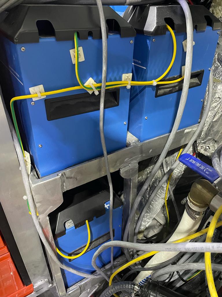
Our three by 7kW 24VDC Lithium house batteries are from MG Systems. Victron Cerbro GX controller monitors these batteries via the MG Systems Battery Management System.
The house battery charging current is limited to 80 amps per battery as the in-feed power < 2kW (MGN280) regardless of other safeguards. For this, we have used the VE Direct CAN comms system and a facility tagged DVCC (Distributed Voltage and Current Control). It was cheaper and a lot simpler than providing a dedicated, fire-resistant, and externally vented containment.
Engine starter batteries are deep cycle lead acid type. They charge from the John Deere engine alternators, plus a small trickle charger as a backup. It's their only job so our engines become self reliant (dead-ship).


A dedicated battery at the helm station ensures extended VHF (GMDSS) emergency calling. Navigation equipment is electrically isolated from any other 24VDC system using a small Victron DC/DC converter. This converter is galvanically isolated and short-circuit protected (think lightning).
Excess power capacity on the 24VDC system (from solar or shore power) can also trickle back through the MultiPlus to three-phase distribution and, from there, slowly recharge the two by 60kWh main power batteries if the Praxis hybrid power system is live. So we now have three ways to keep a charge those huge power batteries (I just checked if that was working, and it is!). Of these three, direct charging from the 70kW Praxis hybrid drive is the quickest.
Power Control and Monitoring
Data transmission from all connected components uses the proprietary Victron VE Direct CAN ethernet, in which all sub-components remain compatible. It is dedicated to only this system. It's a thing of beauty, to be honest, nice design from Victron.


Left is the Cerbro GX. Black connections are the Screen HDMI and power. Blue are the 3 VE CAN with a CAN termination block to the right of them.. Solar output is shown in the photo above, right, at 1231kW, that is the maximum system requirement at that specific moment. 967W is charging house batteries as the system went live overnight, 175W going to DC consumers and a small trickle going in to warming up the MultiPlus inverters.
The system's hub is the Victron Cerbo GX and a Victron Touch control screen. Both sit at the Helm Station. The GX is a small computer that allows each device to communicate. It does some controlling along the way. Connected to that is the Victron Touch display. We can view and control the system remotely via the Victron VRM Web portal using the Starlink comms system (or not in Turkey!) or locally on a cellphone via the Victron Connect App using Bluetooth. That connection went live yesterday.

How is the head? If it is as bad as mine after writing this, then try this background read from Victron Energy; I found it very helpful: HERE
Chris Leigh-Jones


Our electrician METS (Niazi Bey) identified an unanticipated failure risk. The MultiPlus has a long mean time between failures so we fell in to a self satisfied lull. However as they were synchronized as a bank of three, failure of 1 was failure of 3. In other words we went dead ship within a day or so. Not a great outcome. The answer was a rework of the logic such that the three phase lines could be linked directly with single phase L1,2,3 bypassing the Multiplus. We can then use one of the remaining two MultiPlus as a temporary house battery charger and just keep an eye on charge state until the system can be brought back on line at a later date. Nice catch Niazi.


Comments