
Installing the Hybrid Marine Drive
- Jun 27, 2023
- 3 min read
Our Explorer Yacht, Vanguard, is pushing against accepted yacht-building practices in a few ways. Sometimes this can be fun, taxing the mind and ingenuity of ourselves and our shipyard, Naval Yachts. An example of that would be the recent installation of our Hybrid Drives.
What is a hybrid drive?
Firstly, a quick refresh on what they are for and what they consist of. Hybrid drives are just a fancy description for diesel-electric with big batteries. These systems have been used in Naval and Cruise Ship applications for a few decades but have later found applications in yachts. Don't go down the rabbit hole of believing the hype of electric drive being a GREEN solution. It's fundamentally unsuited for 95% of hull designs because battery energy density dictates a low range. However, there are some advantages.
Silent and subtle manoeuvering with no minimum idle speed allows the implementation of commercial dynamic positioning (DP0).
Huge storage batteries guarantee energy independence.
No additional noisy generators and very rapid (70kW) battery charging.
Driving two propeller systems from a single diesel engine.


From left to right, lower picture (600VDC electric drive motor not included, it fits above the gearbox).
Engine - grey, clutch - red, hybrid drive - green, clutch - grey, gearbox - dark grey, coupling - dark blue.
Our parallel drive line consists of a marine diesel engine (John Deere 4045), a step-down/up DC motor drive line (Esco Power/Praxis), a marine gearbox (Twindisc) brake, and self-aligning coupling (Bruntons). We can run on diesel, electric, or both and drive the electric motor at a full engine speed (2300 rpm) as a vast (70kW!) generator. A system of clutches ensures each element is isolated. Look to the link below for a full description.
Foundations
Firstly the engine foundations, the whole assembly is quite heavy, and with no down angle on the gearbox, it is low in the hull of our explorer yacht. The assembly inclines just 5 degrees aft (see illustration above). Good for stability and propeller efficiency but not providing easy clearances. We also cared to fit self-limiting anti-vibration mounts in case we broach. These flexible mounts have limited travel and keep everything in place. Not all mounts are made this way, so be careful.


Engines and driveline

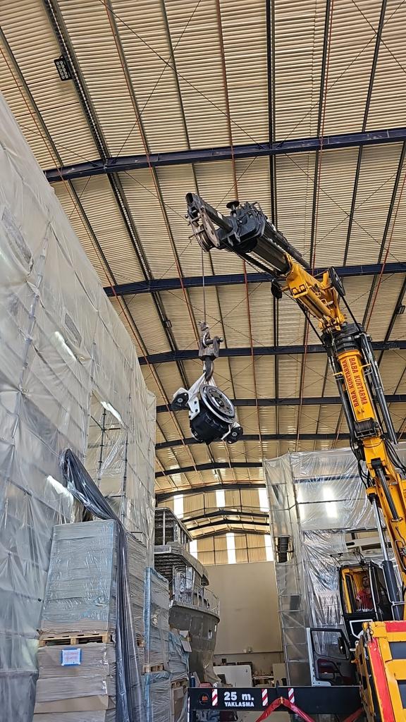
So now the time has come to install the engines, drivelines, shafts, and self-pitching propellers (Bruntons). And boom! We ran into our first issue. As delivered, in error, the gearboxes had a 10-degree down angle on the final drive instead of parallel (0) degrees. Luckily we managed to source two suitable gearboxes from the USA; they are common in commercial fishing fleets.
Three weeks later, we were able to start. Engines, step-up hybrid drives, and gearboxes were connected to form a single monolithic component. The John Deere engine flange is SAE (3) with 12 equispaced fixing holes allowing radial symmetry on the connection. We did play with orientating the drives at 30 and 60-degree angles but ultimately decided vertical was the best use of space and the most straightforward option. This also keeps the 600VDC motor cables well clear of the bilges! However, we needed to move the engine air intake filter to a clear location. I note FPB 64's also relocated this filter (for unknown reasons).
Shafts and skegs
Skegs were prepared next for the stern tubes. These were aligned with the engine assemblies, firstly with piano wire and then an industrial laser before welding in place. The propeller shafts are supported by bearings that are set into this shaft. Alignment is maintained with epoxy chock compound, allowing accurate positioning before set-up. Additional protection is provided via a Bruntons self-aligning shaft coupling (maximum of 3 degrees misalignment, we expect much less than that).


Finish
So now we have the engine, hybrid drive, gearbox, and shaft coupling installed and ready for all the ancillary components. Shafts, propeller bosses, and line cutters are on the shop floor awaiting installation, as are the shaft brakes that cause the Bruntons Autoprops to feather when not rotating. Rudders are also completed and are now ready for fitting into the hull. Propellers can be removed with rudders in place, but we must drop them to remove the shafts.
Chris Leigh-Jones


Comments